International Journal of Medical Sciences
ISSN: 1449-1907
3.2
Impact Factor
ISSN: 1449-1907
- Current Issue
- Volume 22; 2025
- Volume 21; 2024
- Volume 20; 2023
- Volume 19; 2022
- Volume 18; 2021
- Archive
- Editorial Board
- Cover Images
- Index & Coverage
- Cover Suggestion
- Special Issues
Top
Introduction
SwRI Human Head Surrogate (HHS)
Non-Perforating Ballistic test...
Non-Perforating Ballistic...
Key Results and Data Summary
Summary and Conclusions
Acknowledgements
References
Introduction
SwRI Human Head Surrogate (HHS)
Non-Perforating Ballistic test...
Non-Perforating Ballistic...
Key Results and Data Summary
Summary and Conclusions
Acknowledgements
References

 Global reach, higher impact
Int J Med Sci 2014; 11(5):409-425. doi:10.7150/ijms.8079 This issue Cite
Research Paper
Dynamic Response Due to Behind Helmet Blunt Trauma Measured with a Human Head Surrogate
Christopher J. Freitas1 ![]() , James T. Mathis1, Nikki Scott1, Rory P. Bigger1, James MacKiewicz2
, James T. Mathis1, Nikki Scott1, Rory P. Bigger1, James MacKiewicz2
1. Southwest Research Institute, Department of Engineering Dynamics, 6220 Culebra Road, San Antonio, TX 78238, USA.
2. U.S. Naval Health Research Center, San Diego, CA, USA.
Received 2013-11-7; Accepted 2014-2-12; Published 2014-3-8
Citation:
Freitas CJ, Mathis JT, Scott N, Bigger RP, MacKiewicz J. Dynamic Response Due to Behind Helmet Blunt Trauma Measured with a Human Head Surrogate. Int J Med Sci 2014; 11(5):409-425. doi:10.7150/ijms.8079. https://www.medsci.org/v11p0409.htm
Other stylesAbstract
A Human Head Surrogate has been developed for use in behind helmet blunt trauma experiments. This human head surrogate fills the void between Post-Mortem Human Subject testing (with biofidelity but handling restrictions) and commercial ballistic head forms (with no biofidelity but ease of use). This unique human head surrogate is based on refreshed human craniums and surrogate materials representing human head soft tissues such as the skin, dura, and brain. A methodology for refreshing the craniums is developed and verified through material testing. A test methodology utilizing these unique human head surrogates is also developed and then demonstrated in a series of experiments in which non-perforating ballistic impact of combat helmets is performed with and without supplemental ceramic appliques for protecting against larger caliber threats. Sensors embedded in the human head surrogates allow for direct measurement of intracranial pressure, cranial strain, and head and helmet acceleration. Over seventy (70) fully instrumented experiments have been executed using this unique surrogate. Examples of the data collected are presented. Based on these series of tests, the Southwest Research Institute (SwRI) Human Head Surrogate has demonstrated great potential for providing insights in to injury mechanics resulting from non-perforating ballistic impact on combat helmets, and directly supports behind helmet blunt trauma studies.
Keywords: helmet blunt trauma, human head surrogate
Introduction
Current generation composite, light-weight, combat helmets provide enhanced fragmentation and ballistic protection, generally with reduced weight in comparison to previous generations of combat helmets. Previous generations of military combat helmets, such as the US Personal Armor System Ground Troops (PASGT) helmets were made solely of aramid fibers, specifically Kevlar, and generally weighed 3.6 lbs (1.6 kg). The current generation of composite combat helmets may weigh as much as 15% less than the PASGT helmets. These new generations of helmets are composite laminate structures which may still include Kevlar but the addition of an updated generation of materials based on Ultra-high Molecular Weight Polyethylene (UHMwPE) fibers such as Spectra or Dyneema have resulted in their improved ballistic performance. In general, increased helmet weight implies increased stiffness due to either more layers of composite materials such as Kevlar or increased matrix or resin mass. Helmets with higher structural stiffness tend to manifest less dynamic back face deflection during ballistic impact. As the helmet weight is reduced, stiffness tends to also decrease, and thus the current generation of combat helmets tends to exhibit greater back face deflection for the same ballistic impact conditions as for the previous generation of helmets. Achieving equivalent ballistic protection (in terms of perforation or projectile defeat) at a lighter weight is a significant achievement; however, the tradeoff of greater dynamic back face deflection at reduced weight may result in other damage or injury mechanisms, such as blunt trauma injuries, coming to the forefront. As a result, behind helmet blunt trauma injuries resulting from non-perforating ballistic impact of fragments or bullets has become a concern to the warfighter and the designers of their personal protection equipment (PPE).
Behind Helmet Blunt Trauma (BHBT) and Behind Armor Blunt Trauma (BABT) are injuries to the human body that result from back face dynamic deflection of the PPE armor system (helmets or body armor such as ESAPI [1]) responding to an impulsive load due to ballistic impact of a projectile. BHBT/BABT results from non-perforating ballistic impact to the armor by the threat projectile, which means that the armor system has successfully defeated or stopped the threat. However, with the development of a new generation of PPE armor materials that have increased strength and toughness with lighter weight (resulting in significantly increased ballistic mass efficiency), the propensity for blunt trauma injuries due to back face dynamic deflection has increased. For most helmet and body armor systems there is limited space available for significant back face deformation or deflection under ballistic impact to occur without the armor impacting the head or torso of the human body. In the case of combat helmets, pad suspension systems have been designed with the objective to attenuate blunt head impact forces, but the intensity of impact conditions used to design the suspension systems are significantly lower than that due to ballistic impact. They typically are designed for motor vehicle accidents, tripping and falling accidents, and parachutist impact conditions, where the impact velocity range is only from 10 ft/s to 14 ft/s (3 m/s to 4.3 m/s) [2]. These types of impact conditions are fundamentally different from ballistic impact and the dynamic interaction that results between the helmet back face and the human head and cranium. For the case of accidents as cited above, where the head and helmet have an initial velocity and rapid deceleration is the primary injury concern, has ultimately resulted in the development of the Wayne State Tolerance Curve [3, 4] as well as other criteria such as the Head Injury Criteria (HIC), the viscous criterion, angular rotation thresholds, translational acceleration limits, and head impact power. It is commonly accepted that skull fracture may be related to maximum dynamic force or impulse; however, there is no consensus on the criteria to use to resolve the full spectrum of possible head injuries due to the range of different injury mechanisms. Thus, to date, no equivalent injury criteria based on design guidelines for combat helmets have been developed to specifically address BHBT due to ballistic impact. The current requirement for ballistic transient deformation for the US Army's Advanced Combat Helmet [5] and the US Marine Corps' Enhanced Combat Helmet [6] is no greater than 0.63-in (16.0 mm) in Roma Plastilina clay. To the authors' knowledge there is no correlation between level of injury and this requirement for maximum ballistic transient deformation.
BHBT injuries have been observed in the field and in laboratory testing on Post-Mortem Human Subjects (PMHS). PMHS tests of non-perforating ballistic impact to the head protected by a helmet have shown injuries ranging from skin lacerations to extensive skull fractures and brain damage [7]. In general closed skull fracture may be classified as simple (linear), basilar, or depressed. A simple or linear fracture is a break in the skull that is not displaced and may penetrate the entire thickness of the skull. Simple or linear fractures are the most common type of skull fracture and are caused by low-energy, blunt force trauma over a wide area of the skull. Basilar skull fractures are linear fractures, but occur at the base of the skull and are associated with more severe trauma due to longer duration impulsive loads. A depressed skull fracture is one in which the segments of fractured cranial bone is pushed inward or is crushed and may subsequently compress the brain. Depressed skull fractures result from high-energy blunt force trauma to a small area of the skull. From a clinical perspective head injuries are defined as critical, moderate, and minor; where critical is associated with long duration (hours) loss of consciousness, intracranial hemorrhaging and cerebral contusion; moderate is associated with skull trauma with or without dislocated fractures and brief loss of consciousness; and minor is associated with superficial fractures and no loss of consciousness. For dynamic conditions resulting from ballistic impact to the head/helmet system, all of these levels of blunt trauma injuries are possible. Ballistic impact to combat helmets by fragments and bullets are typically a high-speed, low-mass event. However, the physical characteristics of the helmet itself (materials and layup configurations) tend to transform the impact to a reduced speed, slightly greater mass event with increased areal coverage due to the dynamic progression of the deflection and delamination of the back face materials of the helmet as it interacts with the projectile. The characteristics and understanding of the mechanics of this transfer of energy and momentum from the strike face to the back face of the helmet is critical to PPE designers, and the subsequent interaction of the dynamic back face deformation with the head and cranium are critical to warfighter survivability.
To address all these concerns a research project was initiated to develop a methodology for evaluating BHBT in a consistent, reproducible, and validated approach. This project was funded by the US Office of Naval Research (ONR) as part of a Future Naval Capability (FNC) program called LIMBR - Lightweight Individual Modular Body armoR. The cornerstone of the experimental methodology developed in that effort is a high fidelity, Human Head Surrogate (HHS). This human head surrogate fills the void between Post-Mortem Human Subject testing and commercial ballistic head forms such as Biokinetics' Ballistic Load Sensing Headform. The void that the Human Head Surrogate fills is that which exists between full biofidelic systems such as provided by cadavers (PMHS) and at the other extreme, non-biofidelic, mechanical head forms made of metal and elastomers. The SwRI Human Head Surrogate (HHS) is made with actual human craniums and synthetic soft tissues for the brain, dura (the soft tissue between the cranium and brain), and skin, supported by a Hybrid III 50th Male Neck Assembly. The soft tissues are represented by specialized mixtures of ballistic gels with similar density, bulk modulus, and tensile strength to actual tissue. The human craniums are commercially available “processed” craniums which are then “refreshed” to a measured level of ductility consistent with fresh cranial bone. Other researchers have also attempted to improve the biofidelity of ballistic head forms. For example, the Human Surrogate Head Model [8], developed primarily for blast testing, consists of head structures made of biosimulant materials, such as a glass/epoxy mixture for cranial bone, Sylgard silicone gel for the brain, and syntactic foam for facial structures.
The HHS head form incorporates a suite of installed instrumentation with includes surface pressure measurements, intracranial pressures, cranial strains, and head and helmet accelerations. High speed video (Phantom V7) and Flash X-ray imaging are used to provide additional data as well as insights into the highly dynamic response of the head/helmet system. The Human Head Surrogate (HHS) thus provides a unique combination of biofidelity with soft tissue simulants. The HHS is not encumbered by the medical restrictions for the uses and handling of PMHS but incorporates the essential features of PMHS relevant to BHBT testing (specifically, human craniums with pressurized brain and dura). Further, the HHS has a significant level of biofidelity not present in mechanical head forms, specifically the ability to directly measure skull fracture.
This paper then provides a description of the Human Head Surrogate, the methodology for ballistic testing using the HHS, plus a review of representative data for sets of ballistic tests with projectiles or threats which includes: 64-grain (0.15 oz) Right Circular Cylinder (RCC), 9-mm Full Metal Jacket (FMJ), 7.62 x 39 (PS), and 7.62 x 51 (M80) projectiles. For experiments using PS and M80 projectiles, a supplemental ceramic applique is attached to the helmet and allows for high velocity, non-perforating experiments to be conducted with these high energy threats. To date, over 70 experiments have been performed using the HHS. In the tests reported here, the helmet used is the US Marine Corps' Lightweight Combat Helmet (LWH), manufactured by GentexCorp and made of a para-aramid material.
SwRI Human Head Surrogate (HHS)
The HHS uses as a keystone to the design “refreshed” human craniums, supplemented by synthetic soft tissues (refer to Figure 1). The human craniums used in the HHS are processed craniums which may be purchased from many different sources. These craniums are typically dehydrated due to the processing methods used when they are cleaned and dried. Since these craniums are fully processed they are not considered to be human subject testing nor generally require Institutional Review Board approval as is required for PMHS testing. The US Department of Health and Human Services defines the guidelines for human research in the US in the Code of Federal Regulations, Title 45, Part 46, Protection of Human Subjects. Each candidate human cranium that is received from a vendor undergoes a detailed examination to characterize the initial condition and structure of the cranium, including measurement of bone thicknesses, suture integrity, and native fractures due to handling. If the cranium successfully passes this screening and characterization phase, then the cranium undergoes a process to “refresh” it.
Processed cranial bone typically is more brittle than live or fresh bone as a result of the processing procedures; thus it is necessary to develop a method for appropriate rehydration or “refreshing” of the craniums used in the HHS. The objective is to rehydrate or recondition the processed human cranial bone such that its primary characteristics of ductility and strength are similar to “fresh” or live human cranial bone. Several different techniques were formulated and applied to the craniums. Of these different techniques the method that resulted in an appropriate level of ductility is based on the soaking of the cranium for 30-minutes in a Shellac solution (consisting of ethanol, isopropanol, methyl isobutyl ketone, pure shellac and water).
A three-point bend test configuration is used to evaluate the ductility and strength of the various refreshed bone samples based on each refreshment technique that was conceived and applied. These measured results are compared to the same three-point bending test of a “fresh” bone sample (“fresh” bone in a Formalin solution) and to data in the open literature, primarily from McElhaney et al. [9]. In this effort, bending strength and modulus (ductility) are the measures used to assess level of cranial bone refreshment; a third measure that may also be used is fracture toughness [10]. Fracture toughness is not used in this study since reference [9] did not report values for it, and it is the primary source of supplemental data used here. In addition, the authors' believe that if bending strength and modulus values are successfully achieved by the refreshment method, then fracture toughness will be appropriately achieved as well. Figure 2 displays data from the tests performed for each refreshed sample type and the “fresh” bone sample (identified as “FA Bone”), and are compared to the McElhaney et al. data for the quantities of strength (maximum stress) and ductility (modulus). The blue horizontal lines in this figure indicate the range of variability in the McElhaney et al. data, while the red horizontal line is the measured value for the single sample of “fresh” bone (FA Bone) tested in this study. The uncertainty bars associated with each sample data point represents the variability in the measured data for each set of samples used here. It should be noted, however, that these tests did not constitute a statistically meaningful sampling set in that only three or four repeat tests were conducted for each sample type and only one “fresh” bone test was possible due to the size of that sample. The McElhaney et al. results are for a data set of 237 samples. Based on this data and these two measures, we judged the Shellac solution soak technique to be the most appropriate method for refreshing cranial bone for this application. The data for the Shellac solution method is highlighted in Figure 2 by the colored oval. The Shellac solution is a biological fluid secreted by an insect and when applied to the skull is absorbed by the cranial bone. The Shellac solution refreshing method proved to be quite effective in this application and no evidence of brittle bone failure is observed in any of the test results.
Synthetic or surrogate soft tissues are used in the HHS to represent the brain, dura, cerebral spinal fluids, and the external skin. The brain and external skin are manufactured from Perma-gel, a colorless, transparent petroleum-based thermoplastic material with a specific gravity of 0.85 (density of 53 lb/ft3 or 0.85 g/cc) and which at room temperature allows bullet penetrations equal to the FBI-standard 10% 250 A ordnance gelatin at 39.2 ◦F (4 ◦C), which simulates swine muscle tissue. Perma-gel is also calibrated for a penetration of 3.35 inches (8.5 cm) by a 0.177-in (4.5 mm) steel BB shot with a speed of 590 ft/s (180 m/s) [11]. The brain surrogate then consisted of 25 oz (700 g) of Perma-gel plus 25 oz (700 g) of iron powder uniformly mixed into the Perma-gel, resulting in a nominal brain mass of 50 oz (1400 g). Perma-gel is also used to represent the external skin covering the cranium and is molded to the cranium with nominal skin thicknesses ranging from 0.2 to 0.3 inches (5 to 7 mm) depending on location on the head. These skin thicknesses correspond to data reported in [12, 13]. The dura (the soft tissue between the cranium and brain) is simulated by a thick layer of silicon with a nominal thickness of 0.02 inches (0.5 mm), where the typical thickness of the human dura is reported to vary from 0.01 to 0.03 inches (0.3 to 0.8 mm) depending on age of the human. Finally, the cerebral spinal fluids are represented by water pressurized to 0.29 psi (15 mm Hg, 2000 Pa).
Two different versions of the HHS have evolved as the system was developed and the experimental methodology was applied through the execution of testing (see Figure 1). In one version of the HHS a full encapsulation of the head with Perma-gel is developed (a full-face version), fully reproducing the scalp and facial skin features (top right image in Figure 1). Whereas in the second version, only a “skull-cap” of Perma-gel is used and covers the cranium sufficiently to represent the scalp skin covered by the helmet (lower right image in Figure 1) and still accounting for the proper interfacing between the helmet suspension system and the cranial skin. Both versions of the HHS provided similar dynamic results and injury conditions; however, the “skull-cap” version requires less time to assemble than the “full-face” version. In general, the HHS mass, size, and thicknesses of any and all surrogate components are tunable to be representative of actual nominal human tissues as reported in the open literature. Thus, the HHS system (minus the hybrid neck) generally has an average mass of 8.8 lb or 4 kg (with a range of 7.7 lb to 9.9 lb, 3.5 kg to 4.5 kg), where the variability is due to variations in cranium sizes and cranial bone thickness. As shown in Figure 1, a Hybrid III 50th Male Neck Assembly is inserted at the base where the spine normally intersects the cranium. The attachment to the cranium is through a gasketed ring assembly that is torqued sufficiently to maintain a strong connection between the cranium and hybrid neck and eliminate spurious flexure at the contact surface. The attachment is intended to be representative of the intersection of the Atlas and Axis to the head, where the Hybrid III neck assembly represents the cervical vertebrae. The assembled HHS and neck are then rigidly mounted to a steel plate and appropriately angled (to get a normal surface impact) for each test configuration.
Figure 1
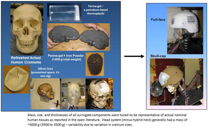
Components of and experimental setup for the SwRI Human Head Surrogate (HHS).
Figure 2
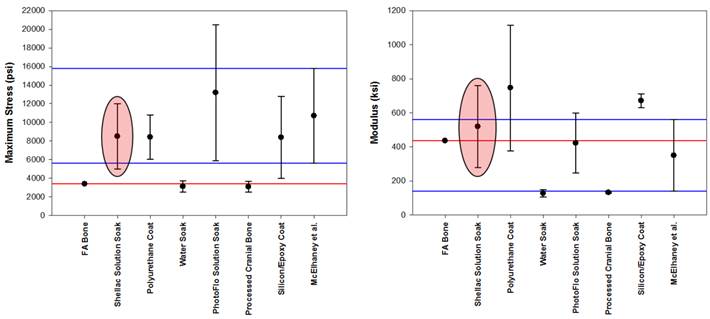
Maximum stress and modulus measured in 3-point bending tests for cranial bone that has been refreshed by different techniques.
The HHS includes a suite of embedded instrumentation for measuring intracranial pressure, cranial strain, and tri-axial accelerations. Traditional piezoelectric pressure transducers and fiber-optic (Fabry-Perot style) gauges were initially used in the HHS. However, the fiber-optic gauges were abandoned due to their fragility (repeated breakage of the fiber during installation or testing), but are a sensor type with great potential application in this context and will be revisited in a future effort. Kulite HKS-375 class pressure transducers were finally selected to measure intracranial pressures. The four gauges are embedded directly into the surrogate brain and are positioned to measure incident pressures; that is the sensing element of the transducer is flush-mounted with the brain surface. A gauge is placed in each of the four quadrants of the brain; i.e., front-0◦ (gauge P1 in Figure 3), back-180◦ (gauge P3), right-90◦ (gauge P2), and left-270◦ (gauge P4) with these angles in reference to the front, centerline of the brain. Figure 3 shows all of these details. These pressure gauges then measure the over-pressure generated in the cerebral spinal fluid that surrounds the brain and is contained within the surrogate dura. The measured over-pressures result from the dynamic deflection of the cranium due to interaction with the dynamic back face deflection of the helmet materials.
Figure 3
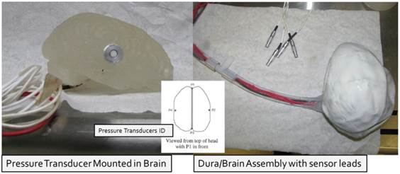
Intra-cranial pressure transducer deployment method - Left image shows transducer embedded in surrogate brain - Right image shows brain, transducers, and electrical leads all sealed inside the Surrogate Dura.
Figure 4 displays the method for deploying tri-axial strain gauges for measuring cranial bone strains during ballistic impact. A total of 12 gauges are typically installed per HHS, arranged in groups of three gauges deployed in a triangular pattern around the anticipated impact or target points. In the tests conducted to date 5 hit points on the helmet are selected; i.e., frontal, crown, back, left side, and right side, all in reference to the normal human descriptions (left ear, right ear, etc.). The gauges used are Tokyo Sokki Kenyujo Model FRA-3-350-11 60◦ rosettes and have a range of 3% maximum strain. As shown in Figure 4, the gauges are bonded directly to the refreshed cranium and the surrogate skin is then molded over the gauges. Based on test results, the bonding method for the strain gauges to the cranial bone did not alter or affect cranial fracturing in the surface areas where gauges are applied. Finally, two tri-axial accelerometers are installed with one gauge mounted in the surrogate (attached to the hard palate) and the other attached to the helmet (attached to the outer surface of the back of the helmet). These two accelerometers are Measurement Specialties, Model 53-0500-360, and had an operational range of 20-1500 Hz. Figure 5 shows the installation and directional orientation of both accelerometers. Data from all these gauges are captured in digital form using a Dewetron DEWE-4102 high-speed data acquisition system with a sampling rate of 1 million data points per second.
Non-Perforating Ballistic test Methodology
The non-perforating ballistic test method used here is similar to that defined in the US NIJ-STD-0106.01 [15]. The objective of this test methodology is to study the effect of back face deflection of the helmet due to non-perforating ballistic impact, and thus an invalid test is one where the projectile perforates the helmet. Thus, great care is taken in this study to ensure no perforations occur. In the test method, the HHS system is rigidly attached to a mounting plate, rather than a mobile stand as specified in the NIJ standard. This approach is appropriate for this application because a Hybrid III neck assembly is used to mount the head to the mounting plate rather than using a rigid cylinder as specified in the NIJ standard. The Hybrid III neck is designed to provide appropriate reaction to dynamic loads as would a human neck under crash applications and has been used in ballistic test research with other head forms, such as Biokinetic's Ballistic Load Sensing Headform [14] . Figure 6 shows a typical experimental setup for a ballistic impact test.
The impact velocity of the projectile is measured using two ballistic light screens placed 1 meter apart. A digital chronograph connected to the screens measures the time the projectile breaks the light beam at each screen and the projectile velocity is then calculated based on the time difference. Projectiles are fired from a universal gun mount system placed 2 meters in front of the first light screen, with the HHS and mount assembly placed 2 meters behind the second light screen per reference [15]. High speed video is used to further document each experiment. Here Vision Research's Phantom V7 high-speed cameras are used with frame rates ranging from 15,000 to 250,000 frames per second, where the frame rate is dictated by the purpose of the specific test. All projectiles are spin stabilized by using rifled gun barrels and their flight characteristics are confirmed through high-speed video imaging. In addition, a separate series of tests are executed in which flash X-ray imaging is used. Here two Pulserad 150 kV (Model 43731A) flash X-ray tubes or heads are deployed in which one is viewing the dynamic event from the side of the test article, while the second tube views the event from the top looking down (see Figure 6). During these tests, two copper wires are laid along the centerline of the helmet and HHS. The first copper wire is attached directly to the cranium so as to more clearly outline the headform and the second copper wire is attached to the inside surface of the helmet to more clearly define the back face of the helmet surface. Calibration tests for each projectile and velocity range are performed to measure the elapsed time from when the projectile exits the final timing screen to the instant of maximum back face deflection of the helmet. These elapsed times are then used in the HHS tests to define the timing delay for when the flash X-ray images are to be taken. Figure 7 displays the initial experimental setup conditions as visualized by flash X-ray imaging.
Figure 4
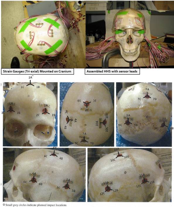
Method for installation of tri-axial strain gauges displaying locations of all 12 gauges.
Figure 5
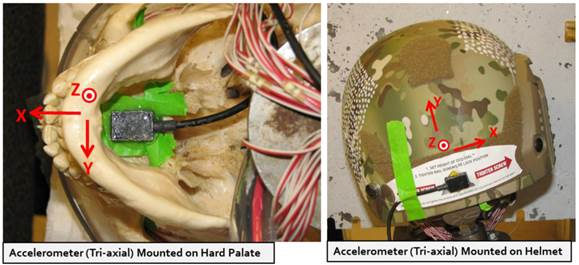
Tri-axial accelerometer installation and orientation.
Figure 6
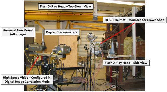
Experimental setup for a typical HHS test.
Figure 7
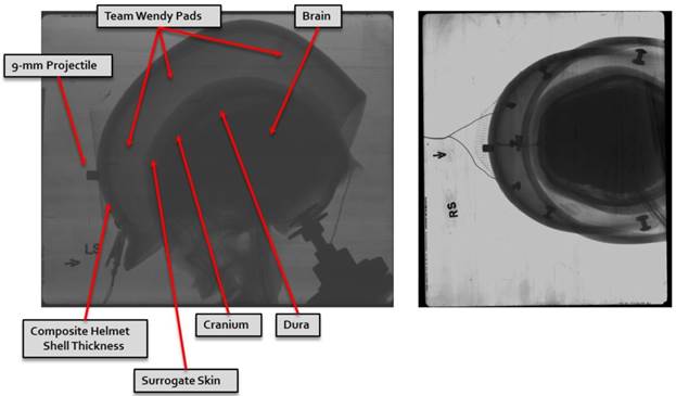
Flash X-ray Image - Left image is side on view (left side) - Right image is top down view.
As with most ballistic test articles, the HHS is not generally intended to be used in multiple experiments but is rather a single shot test item. However, dependent on the test conditions, the HHS may be used in multiple experiments. The procedure for determining whether a specific HHS may be used in another experiment consists of removing the skin from the cranium and comparing the bone's condition to the original cranium characterization performed when the cranium was first received. If no fractures have developed anywhere on the cranium and all sensors are still operating within calibration, then the HHS may be used in another experiment. However, if any minor, surface fractures have resulted from the previous test, then the HHS is retired and disassembled so that the sensors may be used in another HHS.
Non-Perforating Ballistic Experiments
A series of non-perforating ballistic tests have been conducted using the HHS and includes to date, 70 fully instrumented experiments. These tests studied the effects of projectile types, hit locations, pad suspension configurations, and ceramic applique effects on BHBT.
As discussed above, the helmets tested here used a pad suspension system. Team Wendy pads are used in all tests, in either a 5 or 7 pad configuration. The 7 pad configuration is the typical pad layout consisting of pads located at front center, front right, front left, back center, back right, back left, and on the crown. The 5 pad configuration used in this study deleted the front and back center pads, leaving the front right, front left, back right, back left, and crown pads in place. Two impact locations on the helmets are reported in this paper and are (1) front center impact of the helmet and (2) side impact of the helmet. Front center hit locations, depending on pad layout configuration are either supported by a pad (7-pad configuration) or are unsupported by a pad (5-pad configuration). All side impacts are unsupported by a pad since in either the 5 or 7 pad configurations this region of the helmet suspension has no pad deployed. The reader may see [16] for more complete details of the pad suspension system for the Lightweight Fragmentation Helmet manufactured by GentexCorp and is representative of current applications for pad suspension systems.
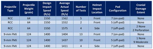
The threat projectiles used in this study are the 64-grain RCC, 9-mm FMJ, 7.62 x 39 (PS), and 7.62 x 51 (M80). The 7.62 PS round has a mild steel core that tends to not undergo significant deformation during impact, while the 7.62 M80 round has a lead core which does undergo significant deformation during impact. Table 1 summarizes the projectile characteristics and the designed target impact velocity for each threat. The RCC projectile was modified to include a skirt which allowed the round to be fired using a .357 Magnum cartridge.
As discussed above, tests were conducted for helmet-only configurations and helmet plus a ceramic applique. The ceramic applique is a surface conforming ceramic supplement to the baseline helmet to provide augmented performance to defeat rifle rounds such as the 7.62 x 39 (PS) and 7.62 x 51 (M80) at or near muzzle velocities. Figure 8 displays the helmet plus ceramic applique layup. These appliques were conceived, designed, and manufactured by M Cubed Technologies. These appliques are composed of a Boron Carbide (B4C) ceramic derivative developed by M Cubed and named BSC-800 ceramic. Two thicknesses of appliques were tested: (1) an applique with a nominal thickness of 0.2-in or 5 mm, and (2) an applique with a nominal thickness of 0.275-in or 7 mm. The appliques are bonded to the helmets using a two-component epoxy system (H. B. Fuller FH-3548). An offset distance of 0.060-in (1.5 mm) between the applique and helmet is used, and is achieved by using wire and glass beads with diameters of 0.060-in (1.5 mm). The appliques tested are ceramic only; however in an actual deployed application, the ceramic will be encapsulated in a polyurea or polyurethane coating with thickness of 0.060-in (1.5 mm), thus the need for the offset distance in these tests.
Table 1
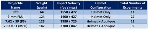
Projectile Characteristics and Test Conditions.
Figure 8
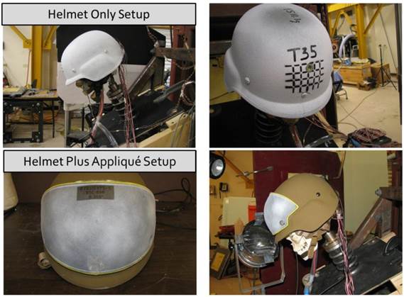
Illustration of Helmet-only and Helmet Plus Ceramic Applique configurations.
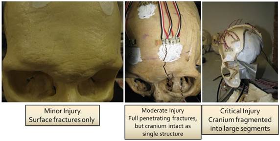
Figure 9
Cranial Damage Categories.
As discussed in an earlier section of this paper, cranial fractures may be simple (linear), basilar, or depressed, and clinical treatments for these head injuries are respectively referred to as minor, moderate, and critical. In this effort cranial damage or fracture is similarly categorized into these three injury classes - minor, moderate, and significant or critical. Minor fractures or injuries are characterized by surface simple (linear) fractures in which the fractures do not penetrate through the thickness of the cranial bone. Moderate fractures or injuries are characterized by full penetrating simple (linear) fractures or fractures that do penetrate through the thickness of the cranium, but the fractures are not dislocated and the cranium is still intact as a single structure. Critical or significant fractures or injuries are characterized by dislocated fracturing, with the condition of the cranium being fractured so as to no longer be a single structure and is fragmented into large pieces or segments. Figure 9 shows examples of each of these classes of cranial injury as identified in this study.
Key Results and Data Summary
Tables 2 and 3 summarize some of the key results from the experiments for the helmet only configurations. Of the 38 fully instrumented tests reported here for the helmet only test conditions, 9 or 24% of these experiments result in fracturing characterized as moderate. These moderate fracturing or injury conditions all are from experiments where the impact location is front center and with a 5-pad configuration (no pad support, off-pad hit). The threat projectile is the 9-mm FMJ shot at an average speed of 1437 ft/s (438 m/s). For the conditions of a front center hit location with a 7-pad configuration (so on-pad hit with pad support), and again with a 9-mm FMJ projectile shot at an average speed of 1404 ft/s (428 m/s), results in no injuries or cranial fractures. No cranial damage is observed for any RCC shots for frontal impacts. Although the average impact speeds of the 64-grain RCC projectiles are approximately 10% greater than for the 9-mm FMJ projectiles, the kinetic energy due to the 9-mm FMJ averages 60% greater than for the RCC projectiles (refer to Table 3). Thus, as suggested by other studies, kinetic energy of the projectile at impact is a critical parameter relating to cranial injury, as well as intracranial pressure [7]. As shown in Table 3, moderate cranial injuries result when the mean peak intracranial pressure achieves a value of 37 psig (255 KPa) resulting from impact of a 9-mm round, which is similar to the values measured in tests with cadaveric heads [7].
The relationship of the suspension pads to the impact location appears to also be important, in that for side impacts, which are off-pad hit locations, no injuries are measured for these rounds. The side impact location is supported, however, by two large pads which provide lateral support to the off-pad region; further there is essentially no curvature to the helmet structure in this region. Thus, the lateral pads provide sufficient support to mitigate deflection in this region, whereas for the front impact location, the helmet surface is highly curved and the lateral pads are separated sufficiently so as to not provide lateral support in the deflected zone. In general, these tests confirm that pads provide an energy dissipation mechanism that helps to mitigate injury for on-pad hits, and that in surface regions of the helmet will little curvature, that lateral pads can also be effective at mitigating injuries for off-pad hits. Note that results from ballistic head form testing confirms that the load on the pad when impacted by a 9-mm round is more spatially distributed, but that the local peak load along the flight path tends to be greater for an on-pad hit versus an off-pad hit [17]. The data in this study shows a different trend, in that on-pad hits with 9-mm rounds results in reduced intracranial pressures and reduced likelihood of injuries in reference to off-pad hits, as discussed further below.
Table 2
Summary of Helmet Only Experiments.
Table 3
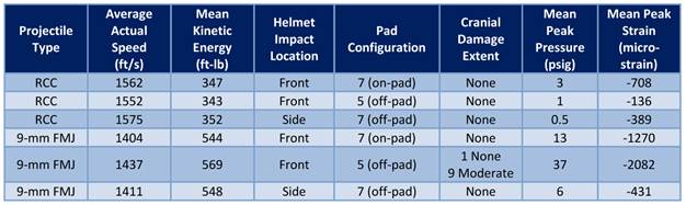
Summary of Key Data for Helmet Only Experiments.
A similar set of tests to those just presented above, 9-mm ballistic experiments for a combat helmet, were performed by Bass et al [18], but with PMHS (cadavers). In their 9 tests, projectile impact velocities ranged from 1312 ft/s to 1509 ft/s (400 m/s to 460 m/s) and all were side impact tests (although not stated, these were likely off-pad hit locations). They observed linear fractures in five of nine tests, with a 50% injury risk occurring at an impact velocity of 1433 ft/s (437 m/s). Bass et al results are similar to those measured here with the HHS, in that moderate injury (linear fractures) result for average impact velocities of 1437 ft/s (438 m/s) or greater for off-pad frontal hit locations.
Table 3 presents the mean peak intracranial pressure averaged across each experiment as well as the mean peak strain measured on the surface of the cranium in the region of impact. For 5-pad (off-pad hit) test conditions that result in moderate injuries, the mean peak intracranial pressure of 37 psig (0.255 MPa) is nearly 3 times greater (2.85 times) than for the corresponding 7-pad (on-pad hit) experiments where the mean peak intracranial pressure is 13 psig (0.090 MPa). The mean peak cranial strains (shown in units of micro-strain in the table) also show a similar trend in that for the 5-pad configurations the measured mean peak strain is -0.21% and is approximately 2 times greater (1.64 times) than the mean value measured in the 7-pad configuration experiments (measured value of -0.13%). The negative values for the strains in Table 3 follow the standard sign convention for strain, and thus these are compressive values. Clearly, the pad configuration is a significant factor in the magnitude of injury to the head. For these dynamic conditions, the pads are able to mitigate dynamic deflection and limit the impact conditions of the back face to the cranium when they are located between the back face deformation and the cranium. However, as presented later in this paper, as the kinetic energy of the projectile increases the ability of the pads to dissipate the back face energy is diminished.
In two of the RCC side impact experiments, the RCC projectile perforated the helmet. From post-test examination of the helmet it is clear that a seam in the laminate layup in the helmet is in this area and thus represents a potential vulnerability of the helmet design for small, non-deforming projectiles such as RCCs.
Tables 4 and 5 summarize some of the key results from the experiments for the helmet plus applique test conditions. Of the 20 fully instrumented tests reported here, 14 of 20 (70%) experiments result in fracturing characterized by critical. Critical fracture injuries developed for 7-pad configurations with the 0.2-in (5 mm) thick applique and 7.62 x 39 (PS) projectiles, and for all test conditions with the 7.62 x 51 (M80) projectiles. In all these experiments, no perforations of the helmet resulted, which is remarkable since these high energy projectiles are all shot at muzzle velocities. In 5-pad configurations, and again using the 0.2-in (5 mm) thick applique and the 7.62 x 39 (PS) projectiles, only minor injuries are observed. This observation is counter to what is measured in the helmet only experiments. Recall that the observations in the helmet only experiments are that the 5-pad configurations result in moderate injuries (the highest level achieved in those experiments) and the 7-pad configuration provided sufficient protection to fully mitigate and prevent injuries. Those observations suggest that for projectiles with lower kinetic energy that the pads are able to absorb and dissipate the load and by so doing mitigate the intensity of interaction between the back face deflection and cranium. However, for the dynamic impact conditions associated with higher kinetic energy projectiles such as the 7.62 rounds, the pads cannot respond quickly enough to either dissipate or distribute the load laterally over a sufficient area, but rather allow for a more intimate and immediate coupling between the helmet shell and the cranium, resulting in critical damage or injury. As shown in Table 5, for these 7.62 projectiles, the 5-pad (off-pad hit) configuration experiments result in reduced intracranial pressures and cranial bone strains. Thus, we observe for 5-pad configurations a reduced level of injury because the pad is not present to provide the direct coupling from the shell to the cranium, and the shell back face deflection tends to be less localized or focused with more lateral spreading of the load. These observations are more fully illustrated in the flash X-ray images shown in Figure 10.
In Figure 10 are shown image sets from three different HHS experiments and they illustrate the characteristics of the peak dynamic deflection event, the back face signature for these helmets, and the response of the cranium to the blunt trauma resulting from back face impact. The flash X-ray technique allows for an instantaneous image at peak dynamic back face deflection based on a delayed trigger time. The top image pair shows the reference state against which the other three sets of images may be compared to. In all four image sets, the left image shows a side view of the event, while the right image shows a top down view of the event. In each image different colored curves are used to identify difference key layers in the helmet and HHS system. The green curve is the outer or strike surface of the helmet shell. The blue curve is the inside or back face surface of the helmet shell. The yellow curve is the outer surface of the skin, while the red curve is the outer surface of the cranium (bone). The experimental test conditions for each image set are described in Figure 10. This sequence of images clearly demonstrates the benefit of pads for the 9-mm projectile impact in which for the on-pad condition the amount of back face deformation is significantly less than for the off-pad result (compare the shape of the blue and yellow curves in the different images). The on-pad test shows no injury, while the off-pad hit results in moderate injury. Further, the M80 projectile result keenly illustrates the concern with BHBT in that although the projectile is defeated by the armor system a significant amount of traumatic load is transmitted to the cranium resulting in critical injury. This threat is currently an over-matching threat for this helmet in terms of BHBT, and regardless of pad configuration, results in significant or critical injuries.
Table 4
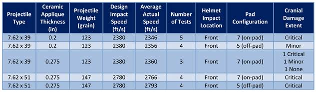
Summary of Helmet Plus Applique Experiments.
Table 5
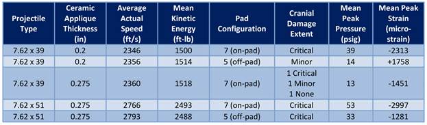
Summary of Key Data for Helmet Plus Applique Experiments.
Figure 10
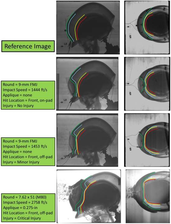
Flash X-ray Images - Left image is side on view (left side) - Right image is top down view.
In Table 5 a similar summary of key mean data as that presented in Table 3 is shown, but for the helmet plus applique experiments. For conditions resulting in critical damage or injuries to the cranium, the mean peak intracranial pressures are again approximately 3 times greater than for conditions that result in minor damage. The greatest cranial bone strains are measured for the 7-pad (on-pad hit) configurations with the 5-pad (off-pad hit) configurations having strains that are 24% (for 7.62 x 39 projectiles) and 57% (for 7.62 x 51 projectiles) less than for the corresponding 7-pad values. This data supports the on-pad versus off-pad hit location observations discussed earlier in this paper.
Figures 11 and 12 respectively display sample intracranial pressure and cranial strain time histories from selected experiments with the HHS. In these figures the data are for four different test conditions, but all are frontal impacts (see figure for specific test details). Pressure gauge locations are shown in Figure 3. The measured pressure response at gauge locations shows the classic signature of a propagating pressure pulse. At some gauge locations, a negative gauge pressure is typically seen in the pressure time histories measured in these experiments and suggests that cavitation of the surrogate CSF (Cerebral Spinal Fluid) may be developing, resulting from the dynamic interaction of the propagating pressure waves transmitted through the CSF from the primary impact location. These negative pressure signals, however, do not show the typical rapid rise to an over-pressure followed by a low-pressure response as the pressure pulse reflects back to the source, which characterizes cavitation in a pipeline. Rather, these pressure histories suggest a more diffused process of pressure propagation from the impact site, where the pressure response is less constrained and damped due to the flexible dura. When critical cranial damage results from projectile impact, the dynamic peak pressures measured at the impact location achieve values significantly greater than 50 psig (0.35 MPa), while for conditions where no cranial or minor damage results, the peak pressure at the impact location is less than 45 psig (0.31 MPa). Further, the mitigating effect of application of a thicker ceramic applique against the same projectile is displayed in Figure 11 where the peak pressure is reduced by a factor of 7 due to the increased thickness of the applique (compare the upper right plot to the lower left plot). Finally, the effect of 7-pad versus 5-pad configurations for similar projectile impacts are shown by comparing the data in the top right and lower right plots of Figure 11. Here, the peak pressures are significantly reduced for the 5-pad configuration (lower right image), when compared to the 7-pad configuration, by a factor of ~10. In these two tests, the 7-pad configuration (on-pad hit) results in critical cranial damage, while the 5-pad configuration (off-pad hit) results in minor cranial damage. As shown in Table 5, the mean peak pressures (averaged across similar tests for each pad configuration - see the values for the 7.62 x 39 projectiles with 0.2-in applique) for 5-pad (off-pad) hit locations are less than for 7-pad (on-pad) hit locations by a factor of 2.8.
Figure 11
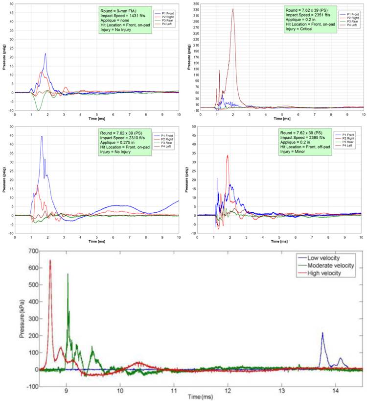
Example of Intracranial Pressure Time Histories (top four plots from this study, bottom plot is due to Liu et al [19]).
Shown in Figure 11 (bottom plot) are results from a set of similar and recent experiments due to Liu et al [19] in which they measured intracranial pressure due to ballistic impact of 9-mm rounds using live, anesthetized pigs. In their tests, they used a flat plate of aramid composites (0.35-in or 9 mm in thickness) to represent a helmet and was the target material impacted by the projectile. The aramid plate was backed by “foam” padding providing a 0.47-in (12 mm) separation between the plate and the pigs head. They grouped impact velocities for the 9-mm rounds into three categories: velocities ranging from low (919 ft/s or 280 m/s), to moderate (1181 ft/s or 360 m/s), and to high (1377 ft/s or 420 m/s). An intracranial pressure sensor was inserted into the brain parenchyma and positioned approximately 0.47-in (12 mm) under the parietal bone and facing the point of impact. For an average impact speed of 1404 ft/s (428 m/s), they measured a mean peak intracranial pressure of 109 psig (0.751 MPa) from a sample set of 8 tests. As shown in Figure 11, the characteristics of the intracranial pressure signals measured in the live pigs are similar to those for the 9-mm projectile results from the HHS (top left plot). However, the magnitude of the mean peak intracranial pressure measured in the live pigs is 3 to 8 times greater than that measured with the HHS for the same threat (refer to Table 3, rows 4 and 5). Liu et al suggested that their high intracranial pressures may have resulted from the lack of scalp used in their tests as well as due to anatomical differences between pigs and humans.
In Figure 12, the cranial strain time histories are measured in the region of the impact location. In these time history plots a negative strain corresponds to compression, while a positive strain is tension. In those experiments in which no or only minor cranial damage occurs, the strain data measured by a rosette shows similar responses in each leg of the rosette, whereas for conditions where fracturing of the cranium results, the strain histories at a rosette location show a dispersion in the signal histories measured by each leg in the rosette. The greater the amount of cranial fracturing that results in a test, the more dispersion in the signal time histories are present. In general, cranial fracturing is observed when dynamic peak strains greater than -0.4% are achieved at the measurement locations.
Figure 12
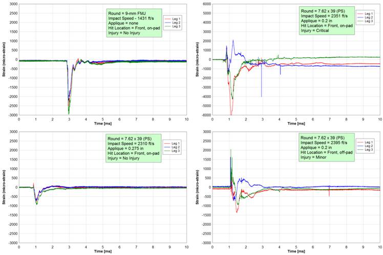
Example Cranial Strain Time Histories Measured During Ballistic Impact Conditions.
Figure 13
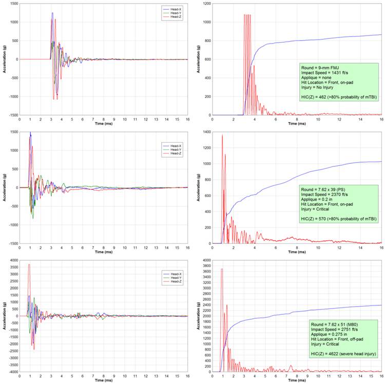
Measured accelerations from selected HHS tests and calculated HIC Results.
Finally, Figure 13 displays head acceleration data from three different HHS tests and are representative of the type of data collected to date. In this figure, the acceleration time histories are shown in the left plots. In the right plots the Head Injury Criterion [3,4], HIC, is applied using the acceleration time history data. HIC is based on the average value of the acceleration over the most critical part of the acceleration event. The average acceleration is defined as the integral of the acceleration time history for a direction of 15 ms. Acceleration in the z-direction (refer to Figure 5) is only used in the calculations here and accounts for primary motion of the head in the vertical centerline plane (essentially nodding of the head with no rotations). The calculated HIC values are shown in Figure 13. A HIC value of less than 519 is equivalent to an Abbreviated Injury Scale (AIS) score of 1, associated with headaches or dizziness, and is a minor injury. A HIC value of 520 to 899 is equivalent to an AIS score of 2 with unconsciousness of less than 1 hour and simple, linear fractures, and is a moderate injury. A HIC value greater than 1860 is typically considered not survivable and has an AIS score of 6. As cited in [18], the use of HIC in assessing BHBT injuries is still under assessment.
Summary and Conclusions
The SwRI Human Head Surrogate (HHS) is developed and applied for assessing behind helmet blunt trauma injuries. This human head surrogate is designed to fill the void between Post-Mortem Human Subject testing which has biofidelity but handling restrictions and commercial ballistic head forms which have little biofidelity but are easy to use. This unique human head surrogate is based on refreshed human craniums and surrogate materials representing human head soft tissues such as the skin, dura, and brain. A methodology for refreshing the craniums is developed and verified through material testing. An experimental methodology based on the HHS is developed and used in a series of experiments in which non-perforating ballistic impact of combat helmets is performed. Sensors embedded in the human head surrogates allow for direct measurement of intracranial pressure, cranial strain, and head/helmet acceleration. Experiments include both baseline combat helmets and helmets with a supplemental ceramic applique for addressing larger caliber threats. Based on a relatively large number of tests, the SwRI Human Head Surrogate has demonstrated great potential for providing insights in to injury mechanics resulting from non-perforating ballistic impact of combat helmets, allowing for a direct measure and assessment of behind helmet blunt trauma injuries.
Acknowledgements
The authors wish to thank the U.S. Office of Naval Research and the Navy Health Research Center for funding this effort and specifically, Mr. Lee Mastroianni.
Competing Interests
The authors have declared that no competing interest exists.
References
1. Cannon L. Behind Armour Blunt Trauma - An Emerging Problem. J Royal Army Medical Corps. 2001;147(1):87-96
2. McEntire JB, Whitley P. et al. Blunt Impact Performance Characteristics of the Advanced Combat Helmet and the Paratrooper and Infantry Personnel Armor System for Ground Troops Helmet. US Army Aeromedical Research Laboratory (USAARL) Report No.2005-12. 2005
3. Patrick LM, Lissner HR, Gurdjian ES. et al. Survival by Design - Head Protection. Proceedings, Seventh Stapp Car Crash Conference. New York: Society of Automotive Engineers. 1963
4. Snyder RG. State-of-the-Art Human Impact Tolerance. Society of Automotive Engineers Technical Paper 700398. 1970
5. Purchase Description Helmet, Advanced Combat (ACH), CO/PD-05-4, Project Manager - Soldier Equipment, Program Executive Office, US Army. 2007.
6. Purchase Description for Enhanced Combat Helmet Version 0.1, PD-ECH-ICE-PG16-0001. 2009.
7. Sarron JC, Dannawi M, Faure A, Caillou JP, Da CJ, Robert R. et al. Dynamic Effects of a 9 mm Missile on Cadaveric Skull Protected by Aramid, Polyethylene or Aluminum Plate: An Experimental Study. The Journal of Trauma Injury, Infection, and Critical Care. 2004;57(2):236-242
8. Merkle AC, Wing ID, Roberts JC. et al. Human Surrogate Head Response to Dynamic Overpressure Loading in Protected and Unprotected Conditions. 26th Southern Biomedical Engineering Conference SBEC 2010, IFMBE Proceedings. 2010 32: 22-25
9. McElhaney JH, Fogle JL, Melvin JW, Haynes RR, Roberts VL, Alem NM. et al. Mechanical Properties of Cranial Bone. Journal of Biomechanics. 1970;3:495-511
10. Roberts JC, Merkle AC, Carneal CM, Voo LM, Johannes MS, Paulson JM, Tankard S, Uy OM. et al. Development of a Human Cranial Bone Surrogate for Impact Studies. Frontiers in Bioengineering and Biotechnology. 2013;1(13):1-8
11. Professional Grade Ballistic Gelatin. http://www.gelatininnovations.com/pages/ballistic_fbi.html
12. Claessens MHA. WFW Report Number 94.003. Eindhoven University of Technology. 1994.
13. Oldendorf WH, Iisaka Y. et al. Interference of Scalp and Skull with External Measurements of Brain Isotope Content: Part 1. Isotope Content of Scalp and Skull. Journal of Nuclear Medicine. 1968;10(4):177-183
14. Biokinetics Ballistic Load Sensing Headform. http://www.biokinetics.com/images/stories/products/blsh/BLS_Headform_-_Brochure.pdf
15. NIJ Standard 0106.01 for Ballistic Helmets. December 1981.
16. Operator's Care and Use Manual for Lightweight Fragmentation Helmet. Gentex Corporation. January. 2008
17. Merkle AC, Carneal K, Wickwire A, Ott K, Freitas CJ, Tankard S. et al. Evaluation of Threat Conditions and Suspension Pad Configurations in Determining Potential for Behind Helmet Blunt Trauma. Proceedings, Personal Armour Systems Symposium, PASS 2010. Quebec City, Canada. 2010
18. Bass CR, Boggess B, Bush B, Davis M, Harris R, Roundtree MR, Campman S, Ecklund J, Monacci W, Ling G, Holborow G, Sanderson E, Waclawik S. et al. Helmet Behind Armor Blunt Trauma. Specialist Conference on Human Factors in Medicine. Koblenz, Germany. 2003
19. Liu H, Kang J, Chen J, Li G, Li X, Wang J. et al. Intracranial Pressure Response to Non-Penetrating Ballistic Impact: An Experimental Study Using a Pig Physical Head Model and Live Pigs. International Journal of Medical Sciences. 2012;9(8):655-664
Author contact
![]() Corresponding author: 210.522.2137, Fax: 210.522.6290, Email: Christopher.Freitasorg.
Corresponding author: 210.522.2137, Fax: 210.522.6290, Email: Christopher.Freitasorg.
Citation styles
APA
Freitas, C.J., Mathis, J.T., Scott, N., Bigger, R.P., MacKiewicz, J. (2014). Dynamic Response Due to Behind Helmet Blunt Trauma Measured with a Human Head Surrogate. International Journal of Medical Sciences, 11(5), 409-425. https://doi.org/10.7150/ijms.8079.
ACS
Freitas, C.J.; Mathis, J.T.; Scott, N.; Bigger, R.P.; MacKiewicz, J. Dynamic Response Due to Behind Helmet Blunt Trauma Measured with a Human Head Surrogate. Int. J. Med. Sci. 2014, 11 (5), 409-425. DOI: 10.7150/ijms.8079.
NLM
Freitas CJ, Mathis JT, Scott N, Bigger RP, MacKiewicz J. Dynamic Response Due to Behind Helmet Blunt Trauma Measured with a Human Head Surrogate. Int J Med Sci 2014; 11(5):409-425. doi:10.7150/ijms.8079. https://www.medsci.org/v11p0409.htm
CSE
Freitas CJ, Mathis JT, Scott N, Bigger RP, MacKiewicz J. 2014. Dynamic Response Due to Behind Helmet Blunt Trauma Measured with a Human Head Surrogate. Int J Med Sci. 11(5):409-425.
This is an open access article distributed under the terms of the Creative Commons Attribution (CC BY-NC) License. See http://ivyspring.com/terms for full terms and conditions.